Our #APP4000 system built for air speeds up to 85 to 200 MPH

Our special 4" blades @ 12" diameter delivers up to 4000 Watts


APP (Air Power Plant)
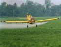


CROP DUSTING POWER PLANT
 
APP's have been used to power centrifugal pumps to pressurize the spray systems on aircraft that are used as crop dusters to deliver liquid agents to cropland. The major reason for choosing the APP system is safety! Using an APP electric generator allows the FAA-certified engine and power systems on the aircraft to remain unmodified. When using the APP for your heavy electric power needs then there is no need to use a power take-off point on the main engine to drive the pump! The pump can be placed low or below the exterior of the airframe greatly simplifying plumbing, and being the lowest point in the plumbing, it will have gravity feed from the spray tanks and never need to be primed. In the event of a pump failure that could result in seizure, the APP has no effect on the flying ability of the aircraft.


SAFETY FIRST! This is the main reason to use the APP type power plants for your crop duster!


#APP4000 -Only $1999.95 plus $74.50 S&H fee.


Here is our famous "APP9000" system

built for air speeds up to 350 MPH speeds.


Special 9" hub with 8" long titanium blades

delivers up to 4000 Watts on deployment.


Military and commercial uses:


4000 WATTS OF EMERGENCY POWER
 
CAN BE USED TO POWER:
 

Can only be deployed at airspeeds under 350 MPH for a full 4000 Watts of power.
Minimum air speed required for operation is 85 MPH which yields 1200 Watts nominal.


What is your air speed and battery voltage? We can design a custom blade length for you.


#APP9000 -Only $3999.95 plus $92.50 S&H fee.


Questions??? For Fast Email Service Email Us Please.
 
For FAST Technical Support Please Email Us Now!
 
and CHECK OUT


NO PAPER company policy. We have no written literature.
Over 175,000,000 tons of paper and other wood products are dumped into landfills annually world over.
We offer only non-polluting electronically generated information that is served here on this web site.


MOST aircraft electrical systems run at 400 hertz instead of the 60 Hz frequency used in the US power grid?
Is it possible to run a piece of 400 Hz electrical equipment on a 60 Hz outlet?
Aircraft design is a series of compromises since engineers must make tradeoffs between optimum solutions that may conflict with one another. The electrical system on an airplane is a good example of just such a tradeoff. The advantage of running an electrical system at 400 Hz rather than 60 Hz is that the power supplies are smaller and lighter. This benefit is important aboard aircraft since space is always limited, and it is imperative to minimize weight in order to maximize performance. This reduction in weight comes at a price, however, since high-frequency electrical systems are less efficient.
Electrical devices on the interior of a corporate jet
Let us now further explore aircraft electrical systems to better understand the significance of these design tradeoffs. The earliest planes had no need for electrical power since they carried no devices that required it. That began to change by the 1920s when planes routinely carried radios and navigation gear powered by direct current (DC) batteries. Later advances led to the development of small generators that supply DC power, typically at 28 volts. Only small general aviation aircraft tend to use DC electrical systems today.
Exterior landing lights on a small plane
By the beginning of the jet age, aircraft were becoming increasingly more complex and operated a vast array of electrical devices. Modern military aircraft are equipped with powerful radars, sensors, weapon systems, and sophisticated cockpit displays that require large amounts of electricity to operate. Commercial airliners too must provide power for environmental systems, galley equipment, cockpit displays, communication gear, weather radar, and in-flight entertainment systems. DC power supplies are insufficient to meet the demands for electricity to operate flight instruments, actuators, heating equipment, avionics, and internal/external lighting on these large aircraft. These planes instead use alternating current (AC) systems that usually supply 115 volts at 400 hertz.
Aircraft are equipped with a number of power generation systems including both primary and redundant backup systems to continue supplying power to vital equipment in an emergency. Primary power is usually provided by AC generators directly connected to the jet engines. Commercial aircraft and many military planes are also equipped with an auxiliary power unit (APU), which is essentially a miniature jet engine that provides an additional power source. The APU is always in operation to supplement the primary power supply or replace it in case of engine failure. If the APU also fails, many aircraft carry an additional ram air turbine (RAT) that can be deployed when needed to provide emergency power. The purpose of a RAT is to keep critical systems operating long enough to land safely.
Auxiliary power unit (APU) of a Boeing 737
These generators provide AC power using an alternator that supplies 115 volts at 400 Hz frequency. The advantage of high-frequency alternators is that they require fewer copper coils in order to generate the necessary electrical current. This reduction in material allows the alternator to become much smaller such that it takes up less space and weighs much less than it would otherwise.
A common rule of thumb in airplane design says that removing one pound of weight can actually reduce the overall weight by at least five pounds because of all the extra structure and fuel that is no longer needed to carry that pound over the range of the plane. This reduction in weight means the plane needs less fuel to travel the same distance so that the aircraft is more economical to operate. Since saving weight is so important to reducing the costs of an airplane, the use of smaller and lighter 400 Hz electrical generators is a significant advantage over 60 Hz electrical systems.
One of the first 400 Hz constant speed drives developed for aviation
The drawback of operating at 400 Hz is that high frequency systems are more likely to suffer voltage drops. The most significant of these losses results from reactive drops. Reactive drops are caused by the inductive properties of the conducting cables or wires through which the electrical current is transmitted. This type of loss is affected both by the length of the conductor as well as the frequency of the power flowing through it. As frequency increases, the larger the voltage drop becomes. At a high frequency of 400 Hz, reactive drops can be as much as seven times larger than at a low frequency of 60 Hz.
This difference in operating characteristics helps explain why the US power grid operates at 60 Hz rather than the 400 Hz systems used aboard aircraft. A lower frequency reduces losses over long distances, like those between a power plant and your home or office. The transmission distances aboard an airplane are very small by comparison, so the power losses are much less significant compared to the reduction in weight of the generation equipment.
Finally, running a piece of 400 Hz equipment on a 60 Hz electrical system is not advised since it will damage the device. If the same voltage is supplied to the 400 Hz device as to a 60 Hz item, it will cause the metal in the 400 Hz unit to overheat. The end result will almost surely be smoke and possibly a fire. This problem can usually be avoided, however, simply by reducing the voltage supplied to the device by a ratio of 60/400, or 0.15. A reduction in voltage to 15% of its original value at the same current will allow most 400 Hz devices to operate safely on a 60 Hz electrical system.


Hit 14610-Times
 
 
ninja-crawler100.webmeup.com